Strokes
These are the attributes for doing stroked lines in PDF graphics.
FigureMaker methods
rescale_lines(scale) [ doc ]
Adjust `self.default_line_scale` by multiplying it by the
given `scale` and adjust the current `self.line_width`
accordingly.
stroke_line(x0, y0, x1, y1, _skip_log_check=False) [ doc ]
Stroke a line connecting (x0, y0) and (x1, y1)

A line is drawn by `move_to_point()`,
`append_point_to_path()`, and `stroke()`.
stroke_polyline(x, y, color=None, type=None, gap=None, close_subpath=None, legend=None, _skip_log_check=False) [ doc ]
Calls `context()`, then, inside the new context, changes
`self.line_type` and `self.stroke_color` (if `color` and
`type` are not None), calls
`append_points_with_gaps_to_path()`, calls `stroke()`, and
then saves the legend information (if `legend` is not None).
Alias for `show_polyline()`.
FigureMaker attributes
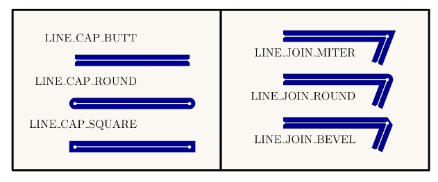
line_cap [ doc | example ]
The line cap style specifies the shape to be used at the ends
of open subpaths (and dashes, if any) when they are stroked.
Valid values are the predefined constants: LineCapButt,
LineCapRound, and LineCapSquare.  For LineCapButt, the stroke
is squared off at the endpoint of the path.  There is no
projection beyond the end of the path.  For LineCapRound, a
semicircular arc with a diameter equal to the line width is
drawn around the endpoint and filled in.  For LineCapSquare,
the stroke continues beyond the endpoint of the path for a
distance equal to half the line width and is then squared off.
See also `self.line_join`.

link:images/Caps_and_Joins.png
Example

line_join [ doc ]
The line join style specifies the shape to be used at the
corners of paths that are stroked.  Join styles are
significant only at points where consecutive segments of a
path connect at an angle; segments that meet or intersect
fortuitously receive no special treatment.  Valid values are
the predefined constants: LineJoinMiter, LineJoinRound, and
LineJoinBevel.  For LineJoinMiter, the outer edges of the
strokes for the two segments are extended until they meet at
an angle, as in a picture frame.  If the segments meet at too
sharp an angle (as defined by the miter limit parameter), a
bevel join is used instead.  For LineJoinRound, an arc of a
circle with a diameter equal to the line width is drawn around
the point where the two segments meet, connecting the outer
edges of the strokes for the two segments.  This
pieslice-shaped figure is filled in, producing a rounded
corner.  For LineJoinBevel, the two segments are finished with
butt caps and the resulting notch beyond the ends of the
segments is filled with a triangle.  See also `self.line_cap`.
line_width [ doc ]
The width of stroked lines.  A line width of 0 denotes the
thinnest line that can be rendered at device resolution: 1
device pixel wide.  However, some devices cannot reproduce
1-pixel lines, and on high-resolution devices, they are nearly
invisible.  Since the results of rendering such "zero-width"
lines are device-dependent, their use is not recommended.  The
actual line width is adjusted according to the current value
of the `self.default_line_scale`.
miter_limit [ doc ]
Sets a maximum for the ratio of the miter length to the line
width (default is 2).  When the limit is exceeded, the line
join is converted from a miter to a bevel.  This limit is
needed since when two line segments meet at a sharp angle and
mitered joins have been specified as the `self.line_join`, it
is possible for the miter to extend far beyond the thickness
of the line stroking the path.
stroke_width [ doc ]
The width of stroked lines.  A line width of 0 denotes the
thinnest line that can be rendered at device resolution: 1
device pixel wide.  However, some devices cannot reproduce
1-pixel lines, and on high-resolution devices, they are nearly
invisible.  Since the results of rendering such "zero-width"
lines are device-dependent, their use is not recommended.  The
actual line width is adjusted according to the current value
of the `self.default_line_scale`.
default_line_scale [ doc ]
Scaling factor for the width of stroked lines (default is 1).
The `stroke()` operations produce lines with a width
determined by the product of the `self.line_width` times the
`self.default_line_scale`.
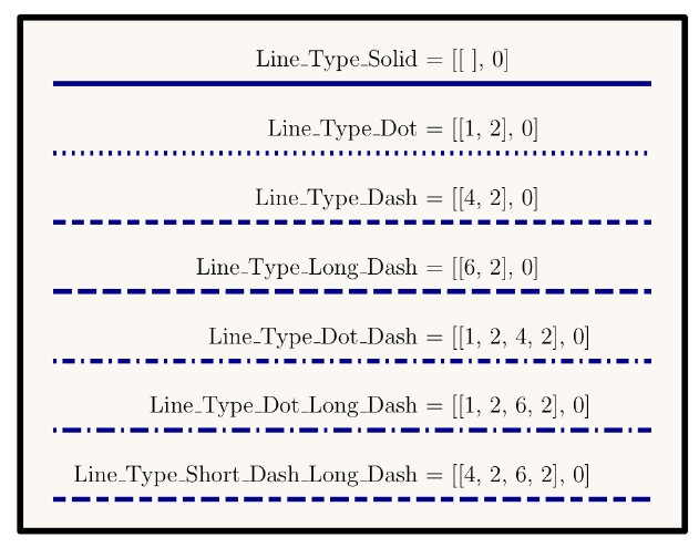
line_type [ doc | example ]
The line type controls the pattern of dashes and gaps used to
stroke paths.  It is specified by a dash array and a dash
phase.  The dash array's elements are numbers that specify the
lengths of alternating dashes and gaps; the dash phase
specifies the distance into the dash pattern at which to start
the dash.  The elements of both the dash array and the dash
phase are expressed in user space units.  An empty dash array
and zero phase can be used to set the dash pattern to a solid
line.

Dashed lines wrap around curves and corners just as solid
stroked lines do.  The ends of each dash are treated with the
current line cap style, and corners within dashes are treated
with the current line join style.  A stroking operation takes
no measures to coordinate the dash pattern with features of
the path; it simply dispenses dashes and gaps along the path
in the pattern defined by the dash array.

When a path consisting of several subpaths is stroked, each
subpath is treated independently -- that is, the dash pattern
is restarted and the dash phase is reapplied to it at the
beginning of each subpath.
Example

PyTioga version: alpha (20071021)
Copyright (C) 2007 Taro Sato & Bill Paxton. All rights reserved.